Choosing the right Permanent Magnet Motor starts with the job it must perform, not a headline efficiency rating. A conveyor, electric pump, and compact robot arm place very different demands on a motor. The right choice should match the actual load, speed range, operating hours, and available power supply. Small details matter.
Begin with the application. Record the required torque and speed, including startup and peak-load conditions. Check the duty cycle, mounting space, ambient temperature, and exposure to dust or moisture. Then review the motor’s performance curves and technical data from its manufacturer. A rated value alone may not describe how the motor behaves across its full operating range. It is easy to overlook this.
Efficiency matters, but it is only one part of the decision. A motor that saves energy may still need a compatible drive, careful thermal management, or more complex controls. Compare total system requirements, service access, expected maintenance, and purchase cost. Confirm that the motor and controller work together under the conditions you expect. If the data is unclear, ask the supplier for clarification rather than guessing.
There is no universal best option. Sometimes the trade-off is less tidy than a product table suggests. This guide explains how to compare motor types, interpret key specifications, assess control and cooling needs, and avoid common selection mistakes. The goal is a choice grounded in application details and verifiable performance, not assumptions.
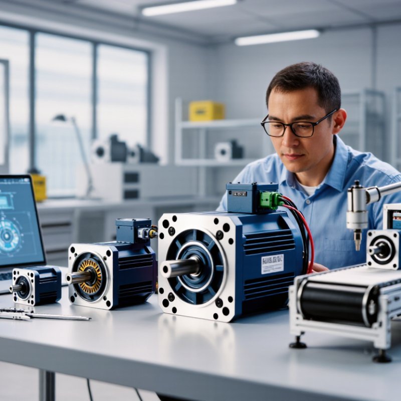
Before comparing permanent magnet motors, describe the job the motor must perform. Record the required speed range, continuous torque, peak torque, and how often the load starts or stops. A conveyor carrying heavy cartons needs different starting torque from a fan running steadily. Brief peaks matter. So does the time between them.
Check the full operating environment, not just the rated power. Note ambient temperature, available airflow, mounting position, dust, moisture, and space around the motor. These details affect cooling and service life. Also confirm the supply voltage, drive compatibility, and any braking or rapid-reversal needs. A motor may meet its nameplate rating yet overheat in a cramped enclosure or at low speed, where cooling can weaken.
Use measured data where possible. Log speed and current during a representative work cycle, including startup and the heaviest load. Then compare those readings with the motor’s torque-speed curve and thermal limits. Estimates are useful, but they can be wrong; a machine’s load may change with product, wear, or temperature. Leave sensible capacity for real operating variation, without choosing an oversized motor by habit. A short test under actual conditions can reveal assumptions that looked convincing on paper.
Use this checklist to define the load, operating environment, and system constraints before comparing permanent magnet motor options. Example values are typical screening references, not final design limits.
| Requirement | What to Define | Example Screening Values | Why It Matters |
|---|---|---|---|
| Application and load type | Identify the driven equipment and whether the load is constant-torque, variable-torque, or constant-power. | Conveyor: approximately constant torque; fan or centrifugal pump: torque generally rises with speed; machine spindle: may require a constant-power region. | The load profile helps determine the motor’s torque-speed capability and suitable control strategy. |
| Rated power and peak demand | Record continuous mechanical output power and any short-duration overload requirement. | A small actuator may use tens to hundreds of watts; industrial equipment may require several kilowatts or more. Specify peak power and its duration separately. | The motor must meet continuous demand without overheating and handle peaks within its specified limits. |
| Speed range | Specify minimum, normal, and maximum shaft speed, including acceleration and deceleration needs. | A geared conveyor may operate below 1,000 rpm at the motor shaft; a direct-drive fan or spindle may require several thousand rpm. Confirm the actual application range. | Speed range affects back electromotive force, drive voltage, cooling, and the need for field-weakening operation. |
| Torque and starting load | Define continuous torque, peak torque, starting torque, and the load torque across the full speed range. | For a rotating shaft, torque in N·m can be estimated from power and speed: T = 9550 × P(kW) ÷ n(rpm). Include friction, inertia, and process loads in the final calculation. | Starting or acceleration torque can exceed running torque, especially with high-inertia or loaded equipment. |
| Duty cycle and operating hours | Record run time, rest time, starts per hour, reversals, and the duration of overload events. | Continuous operation can be described as S1 duty; periodic operation with repeated starting and stopping may require assessment under an intermittent duty cycle such as S3. | Duty cycle determines thermal loading and whether the motor can cool adequately between operating periods. |
| Power supply and drive | Specify available DC bus or AC supply, voltage limits, drive type, current limits, and control interface. | Common DC bus systems include 24 V, 48 V, and higher-voltage industrial buses; the selected inverter must match the motor’s electrical and current requirements. | A permanent magnet motor normally requires compatible electronic commutation and control; voltage and current limits constrain achievable speed and torque. |
| Ambient temperature and cooling | Specify minimum and maximum ambient temperature, airflow, mounting orientation, and available cooling method. | A controlled indoor environment may be around 20–25°C; machinery near furnaces or in outdoor enclosures may encounter substantially higher or lower temperatures. | Winding and magnet temperatures affect insulation life, efficiency, and available torque. Cooling conditions must be included in thermal sizing. |
| Ingress, dust, and moisture | Assess exposure to dust, water spray, washdown, condensation, and corrosive or conductive contaminants. | An indoor dry installation may need basic enclosure protection; dusty or washdown locations may require a higher suitable IP rating, selected for the actual exposure. | Enclosure protection and sealing affect reliability, cooling, maintenance, and suitability for the installation site. |
| Mounting and mechanical interface | Record shaft dimensions, coupling or gearbox arrangement, mounting pattern, radial and axial loads, and available space. | Check shaft diameter and key or spline details against the driven equipment; verify allowable bearing loads and alignment tolerances from motor documentation. | A motor can meet electrical targets yet be unsuitable if its shaft, bearings, mounting, or envelope does not fit the machine. |
| Noise, vibration, and accuracy | Set acceptable noise and vibration levels and determine whether precise speed or position control is required. | A positioning axis may need encoder feedback and repeatable low-speed operation; a general fan drive may prioritize smooth running and acceptable acoustic performance. | Feedback devices, control tuning, mechanical balance, and mounting stiffness can affect system performance and comfort. |
| Safety and compliance | Identify applicable machine, electrical, environmental, and functional-safety requirements for the destination market. | Confirm required electrical ratings, insulation system, protective grounding, and any machine-level safety functions with the project’s compliance requirements. | Compliance depends on the complete motor-drive-machine system and installation, not solely on the motor component. |
Selection note: Treat the example values as an initial checklist. Confirm final ratings, thermal limits, overload capability, enclosure protection, and drive compatibility using the actual load profile and the motor manufacturer’s technical documentation.
Record the required speed range, continuous torque, peak torque, and start-stop frequency. Include the heaviest load.
Temperature, airflow, mounting position, dust, moisture, and available space affect cooling and service life. Small details matter.
Log speed and current during a representative work cycle, including startup and the heaviest load. Estimates can miss changes from wear or temperature.
Surface-mounted magnets sit on the rotor’s outer face. Interior magnets are buried inside it and may support a wider speed range.
No. Control settings and thermal limits still matter, so compare performance across the required speed range.
Radial-flux designs are common and relatively straightforward to integrate. Axial-flux designs can be thin and disc-like, but review cooling and manufacturing constraints.
Peak torque alone does not show how a motor performs in regular use. Ask for efficiency maps and temperature data under relevant test conditions.
Leave room for real operating variation, but do not oversize it by habit. A short test under actual conditions may expose a mistaken assumption.
Choosing the right Permanent Magnet Motor starts with a clear understanding of the application. Identify the required speed, torque, duty cycle, load profile, and operating environment, then compare suitable motor types and configurations. Consider how each option handles starting, acceleration, precise speed control, and changes in load, since these factors influence both performance and system design.
Next, check that the motor fits the available mechanical space and electrical supply, and can withstand expected temperatures, moisture, vibration, and other site conditions. Evaluate efficiency across the motor’s normal operating range rather than relying on a single rating. Also consider control equipment, installation needs, serviceability, expected lifespan, and the cost of energy and maintenance over time. A well-matched motor balances performance, compatibility, reliability, and total ownership cost for the specific application.

 Goaxis Pro